Engineering the amplifier. The development of the amplifier is kindled by the ambition of producing pure and clean transmission of both signals and power, and reproducing the essence of the original signal sources as total as possible.
Approaches
When designing the circuit, not only do we perform endless computer simulation, but also countless real-live performance assessments and ceaseless auditions. Over dependence on one approach may blind many possibilities for improvements. For instance, focusing solely on low distortion of the circuit may sacrifice listening experience. And in this particular example, apparatus and computer simulation can give you a measurement of distortion but not listening experience. Hence, it is necessary to come up with multiple methodologies to cover the blind spots.
Point to Point Connections
The most common solution of building circuitry is by using a printed circuit board (PCB). As we investigate in this standard solution of the industry, we discover that it is impossible to maintain purity during transmission, because of the indirect connections between components. Signals from a component has to first pass through a soldering point, a soldering pad, a thin at copper layer, a soldering pad, and finally to another soldering point again before reaching the next.
This imperfect contact keeps recurring throughout the whole circuitry and reduces the purity of the transmission. The adhesive part which bonds the copper layer to the glass fibre board and the protective coating on the copper layer are inevitable due to the manufacturing process of PCB, which provide a poor environment for the transmission of signals. The quality of the copper of the conduction layer, in terms of purity and crystal structure, cannot be determined and, by our findings, its profile lowers the quality of signal and power transmission.
To achieve the purest and cleanest transmission, we decide not to use PCB. We start considering if we use the usual approach of valve amplifier, components are too far apart and a lot of connection wires are needed. If we directly connect components together, for the small size of solid-state components, it will be an impossible and unsafe work. We finally decide to go for a circuit board which can hold components, giving structural strength and possibility to work on.
We immediately think of PTFE as an alternative, which is famous for its outstanding dielectric property and high stability over environment changes. But we find that it is too soft in nature which causes structural problems when it comes to a larger piece. To solve this problem, we finally come to PEEK, a much more expensive engineered plastic. PEEK is very stable over environment changes and provides excellent dielectric properties. With its hardness and stiffness, it gives a superior condition for amplification.
As a result, all components are attached onto the PEEK circuit board and connected directly to each other without intermediate disturbance, reserving the quality of the original signal. Many soldering points are reduced than before. In our auditions, this approach gives much better purity as well as clean and direct sound. But as a big drawback of the solution, extra days of intensive works to build the circuit by labour and quality check are needed.
Fasteners and Bracing Materials
We then investigate fasteners and bracing materials. It is common to use metal or stainless steel but we raise a big question. We pay attention to the magnetising effect and eddy current. When a signal or current goes through a metal plate, the electric eld will generate a magnetic eld within the metal and this potential energy affects back to the signal. In our test this magnetic eld generates a blur and unclear effect to the sound.
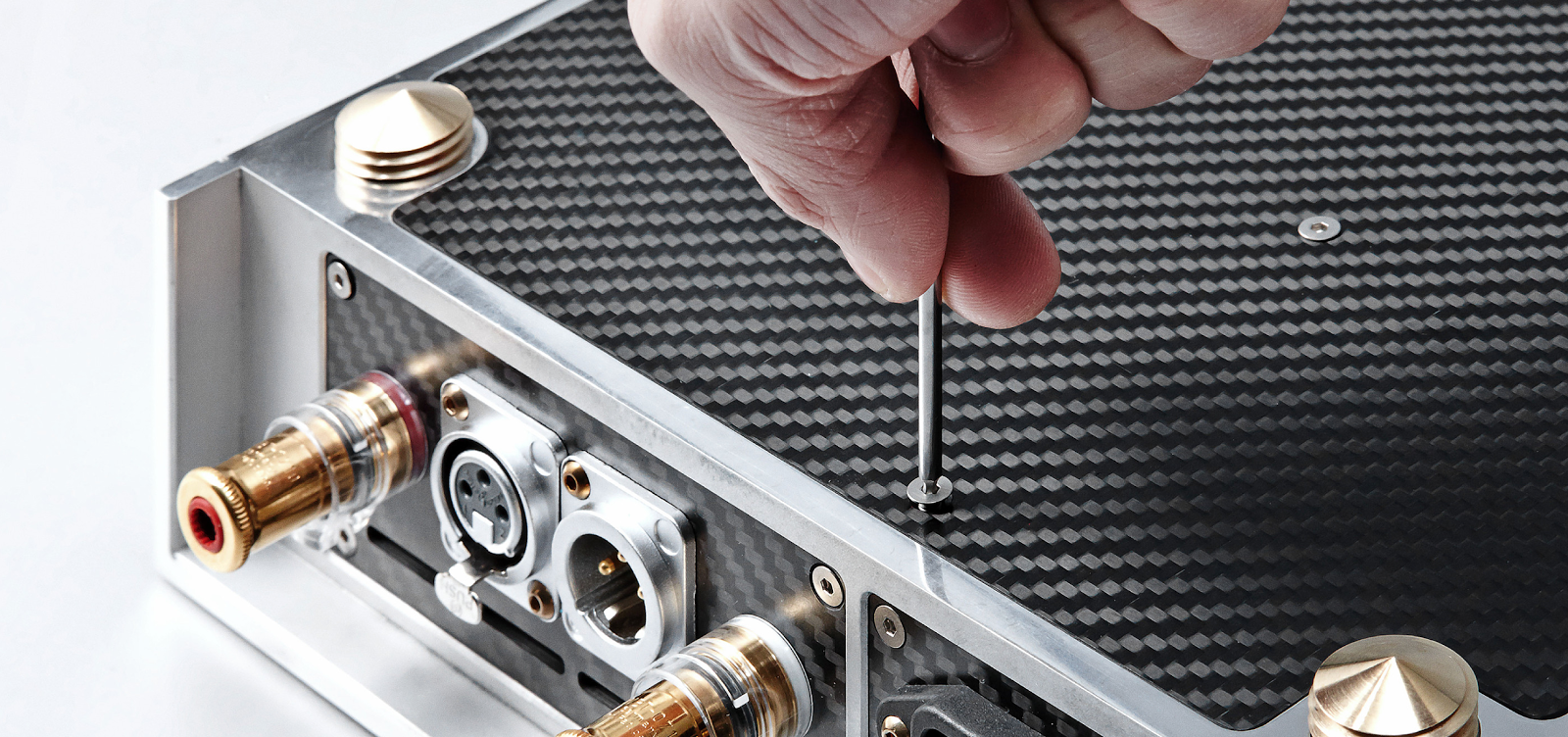
To further increase rigidity and stability of the whole, we decide to go for Titanium screws, in which the yield and tensile strength is higher than common stainless steel screws. Besides, titanium is more environmentally stable than stainless steel. As a result, amplification is under a much more stable environment.
Similarly, for fastening transistors, whenever metal screws are used, it gives a less clear, pure and direct sound after testing several metal screws. What materials can be used if metals cannot be used? No metals. Yet, it has to be strong enough to firmly hold the transistors. Even usual plastic screws cannot do. So we finally make screws with PEEK. As mentioned above, PEEK is hard,stiff and stable with excellent dielectric property, which is perfectly suitable in this application.
As we consider the eddy current on metals, we decide to adopt PEEK screws for the screw terminal capacitors, which solve the issue of eddy current when metal screws are used.
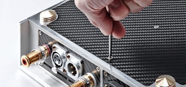
Another problem about metal is that it actually absorbs radio interferences from the environment and these interferences then convert to electrical noise and magnetic disturbance which affect the whole system, giving a blur and noisy background. Therefore, we adopt an extensive use of carbon fibre as shielding materials for both amplifier and cables, instead of the usual copper or aluminium braids and foils, which does not generate any magnetic fields, and amazingly, it rejects interferences without absorption in nature. It also provides a very high stability over environment changes and extreme rigidity which gives low resonance and vibrations.
handling will be much better. We consider that some pre-amplifiers with only one output that cannot connect two or more power amplifiers, or not designed to drive more power amplifiers as input impedance would curtail the original in half. We design a special by-pass for connection to the next power ampli er. With this design users can use several power amplifiers with most of the pre-amplifiers in the market.
Transformer
Toroidal transformers are widely used in the industry. It is efficient and very easy to source.
For transformers we raise two considerations. When we designed the amplifier, we hope to make it smaller and thinner in size so users can easily place two or more amplifiers on the rack and stack. Even not considering power quality, neither EI type, R type nor normal toroidal type transformers can be t inside such small case, with footprint and height limitation. Second consideration is power quality. The O type transformer used in our amplifier provides even higher eficiency than usual toroidal, and a cleaner, purer, faster power due to its different iron core design. O type transformer is simply smaller and better.
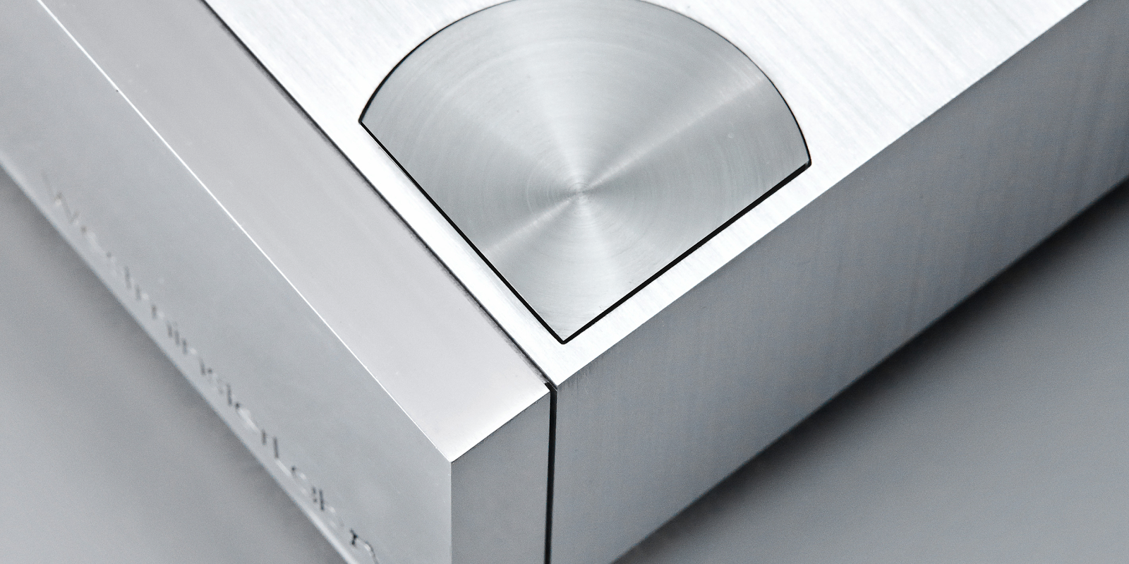
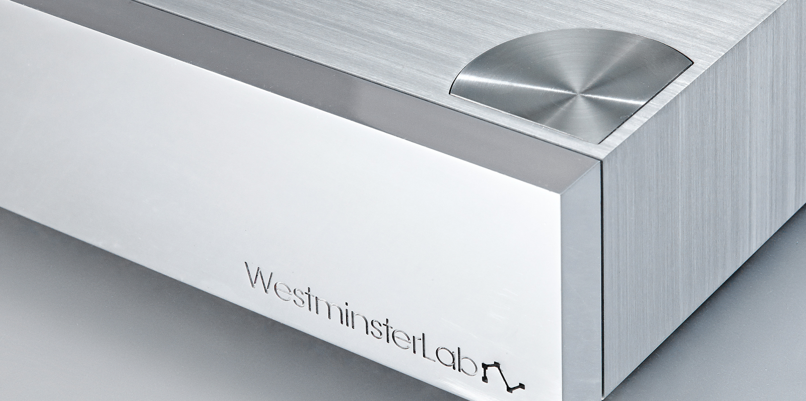
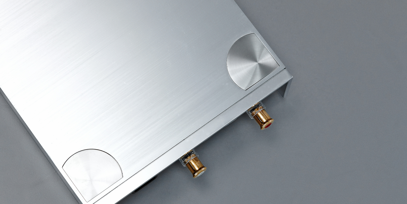
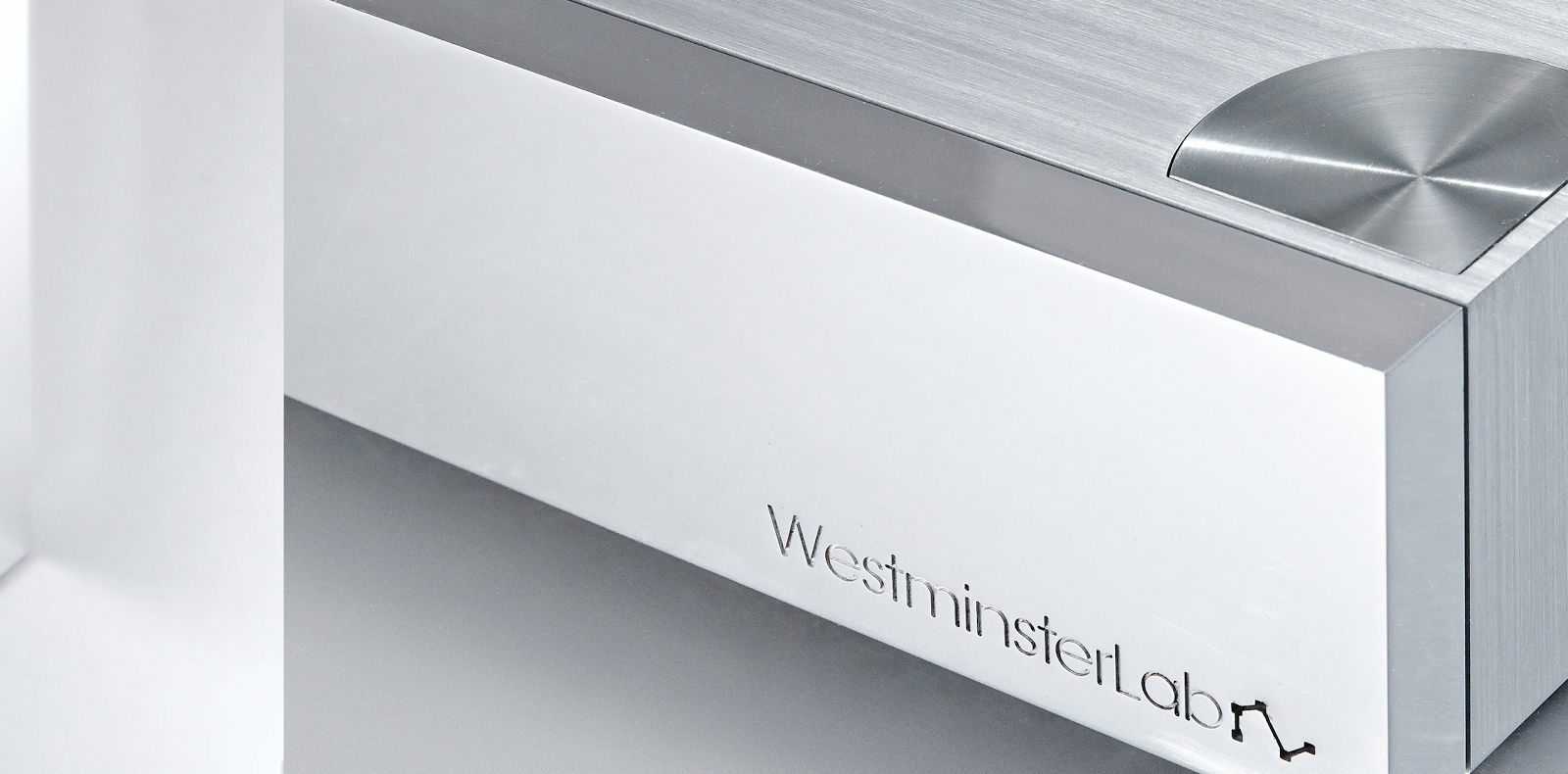
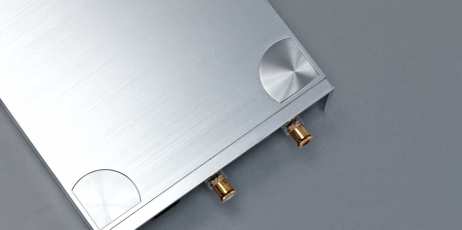
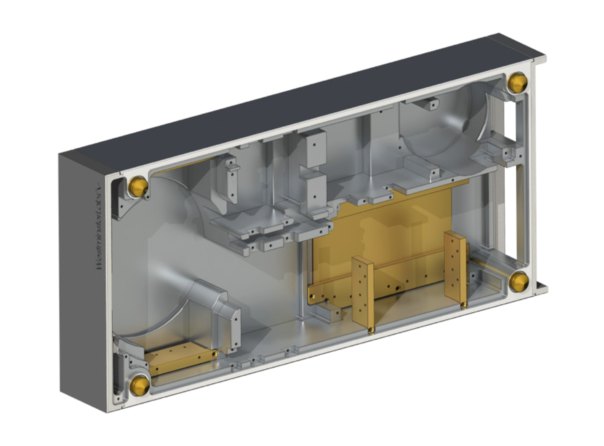
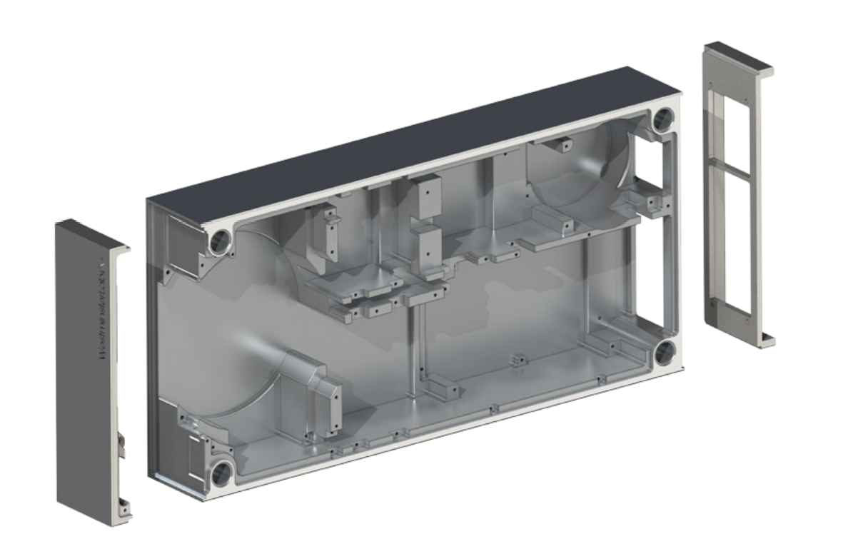
Unibody Construction
As said above, we consider much about the stability and rigidity of the whole ampli er. This is because under a stable environment, signals and power can go through a more stable, undisturbed ow. For that, the chassis must be very stable and rigid with very low resonance and vibration.
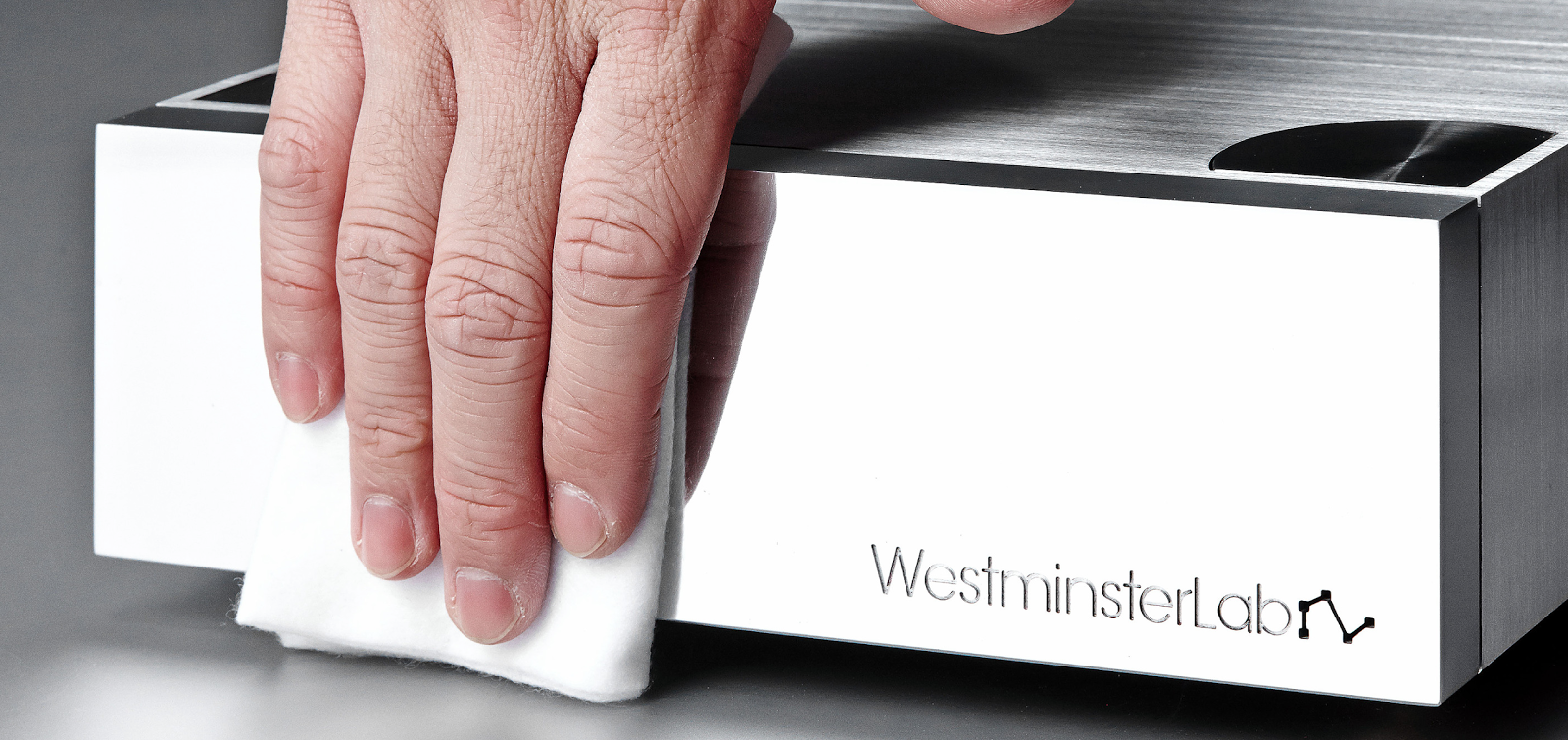
Moreover, wherever there is a joint, there is a possibility of vibration. So as to minimize vibration, we doubtlessly decide to machine the chassis from a 30kg block of 6082 aluminium, which is then machined down to 8kg. The complex structure inside the chassis is designed to allow each component to have its bespoke mounting point on the chassis if possible.
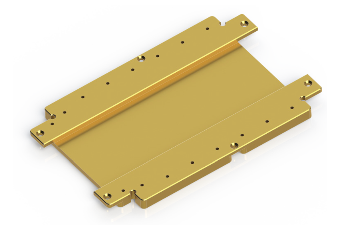
Uni ed Thermal Core
We figure out an improving room when we are installing the power transistors. In the original design the transistors are directly mounted onto the one-piece aluminium chassis. What inspire us is the improvement of the evenness of heat produced by the power transistors. The reason is, the evenness of the power transistors’ temperature contributes closer conditions changes between these transistors and the amplification, providing a much more stable environment. Therefore, we change our design by first mounting the power transistors onto a single piece of copper for both PNP and NPN channels, and then mounting this piece of copper onto the aluminium chassis. The result is excellent. Temperature of these transistors come closer and the output sound is more stable and dynamic.
Conclusion
This is the whole process we engineer the mono ampli er and for certain we will continue exploring the best. Hope all the users enjoy our products and experience music as it is.
Daisy Chain
We understand that the best solution for a speaker system is one amplifier drives only one speaker unit, in which impedance change and power
Power
100 watts @ 8Ω
200 watts @ 4Ω
400 watts @ 2Ω
Frequency Response
1 Hz to 200 kHz, -1 dB
20Hz to 40 kHz, ±0.1 dB
Distortion
(120 watts @ 8Ω)
<0 .1="" 1="" i="" khz="">
Signal-to-Noise Ratio
106 dB, A-weighted
Input
1 balanced XLR input
Output
1 balanced XLR output
Input Impedance
100 kΩ
Output Impedance
0.10Ω
Dimensions
W232 x H72 x D501 mm
Weight
22KG